Flows between rotating disks
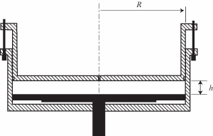
The instability patterns in the flow between rotating disks enclosed
in a stationary cylinder are experimentaly investigated. In our
experimental setup (figure 1), the lower disk (in black) rotates in
the transparent cylindrical cylinder, which may rotate as well. The
instability patterns are characterized by means of simple visualizations
and by Particle Image Velocimetry (PIV).
The experimentaly observed flow patterns are summarized in the regime diagram in figure 2. The horizontal and vertical axis represent the angular velocity of each disk. The aspect ratio of the cell has been fixed to R/h = 21. The yellow and pink areas correspond to the boundary layer instabilities, observed in corotation and weak counter-rotation. The blue area correspond to the shear layer instability, only observed in the counter-rotating flow.
Boundary layer instabilities
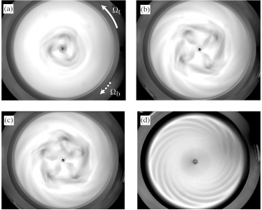
The flow, initialy homogeneous for low rotation rates, bifurcates towards a propagating circular wave state (figure 3). As the rotation rate is further increased, another instability pattern appears, in the form of a set of spiral arms. This pattern is called "positive spirals", because the arms make a positive angle with respect to the azimuthal velocity of the fluid. Circular waves and positive spirals are confined in the inward boundary layer close to the stationary disk
(Gauthier et al. 1999).
Shear layer instability
The flow between counter-rotating disks give rise to a new instability pattern (figure 3), which consists in a polygonal set of vorticies surrounded by spiral arms. (Moisy et al 2003, 2004). The spiral arms now make a negative angle with the azimuthal velocity (Gauthier et al 2002). For low aspect ratios, R/h between 2 and 6, only the central polygonal pattern can be seen, while for larger aspect ratios (R/h > 14) only the spiral arms can be seen.
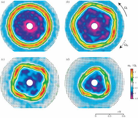
Particle Image Velocimetry measurements allowed us to identify the mechanism responsible for these flow patterns observed in the counter-rotating regime. This velocity measurement technique allows to reconstruct the instantaneous 2D velocity field from image correlations of particles lighted by a horizontal laser sheet between the two disks.
In figure 5, an intense annular shear layer (in red) may be seen, that separates two fluid regions rotating in opposite directions. This shear layer is prone to a Kelvin-Helmholtz - like
instability, that breaks the axisymmetry of the base flow. The spiral arms result from the interaction of the shear layer instability with the outward boundary layer over the faster rotating disk.
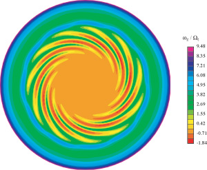
The new class of instability revealed in our experiment has motivated a numerical study of the flow between counter-rotating disks, by O. Daube (CEMIF / LME). Figure 6, obtained for large aspect ratio, shows a spiral pattern in excellent agreement with the ones observed experimentally.
Publications
-
C. Nore, F. Moisy and L. Quartier, Experimental observation of near-heteroclinic cycles in the von Karman swirling flow, Phys. Fluids 17 (6), 064103 (2005)
[Abstract].
-
F. Moisy, O. Doaré, T. Pasutto, O. Daube and
M. Rabaud, Experimental and numerical
study of the shear layer instability between two counter-rotating
disks, J. Fluid Mech. 507,
175-202 (2004). [Abstract].
-
F. Moisy, T. Pasutto and M.
Rabaud, Instability patterns in the flow between
counter-rotating disks, Nonlinear Processes in Geophysics
10 (3), 281-288 (2003). [Abstract].
-
G. Gauthier, Ph. Gondret, F.
Moisy et M. Rabaud, Instabilities in the flow between co and
counter-rotating disks, J. Fluid Mech 473, 1-21
(2002) [Abstract].
-
G. Gauthier, P. Gondret, F.
Moisy and M. Rabaud, Patterns between two rotating disks,
Phys. Fluids 14 (9), S7 (2002) [Gallery 2002 | PDF
(224Kb)].
-
G. Gauthier, Ph. Gondret et
M. Rabaud, Axisymmetric propagating vortices in the flow between
a stationary and a rotating disk, J. Fluid Mech. 386,
105-126 (1999 ). [Abstract].
-
G. Gauthier, Ph. Gondret et
M. Rabaud, Motions of anisotropic particles: application to
visualization of three directional flows, Phys. Fluids
10 , 2147-2154 (1998 ).
[Abstract].
|


 Version française